Leave Your Message



Choosing a Piezoceramic Actuator is less about finding the largest stroke on a datasheet and more about matching motion to the real task. A positioning stage in a clean laboratory may need nanometer-scale resolution, while a valve or optical assembly may prioritize force, speed, and repeatability. The right choice starts with measurable requirements: useful travel under load, blocking force, drive voltage, response time, operating temperature, and available space. Small details count.
Specifications can be easy to misread. Free stroke is not the same as travel under load, and performance can shift with preload, mounting stiffness, temperature, and drive conditions. Compare the actuator, amplifier, mechanical interface, and control method as one system. Check capacitance and current demand, too; a fast command may exceed what the driver can supply. That matters.
The seven tips in this guide help translate application needs into a reliable selection and flag details that often surface during integration. They cover motion and force targets, electrical compatibility, environmental limits, mounting, control, and supplier documentation. Ask for the test conditions behind quoted values. When possible, verify critical measurements in a representative setup. No catalog can predict every installation. I would treat an early choice as a well-supported starting point, not a guarantee; that caution may prevent an expensive redesign later.
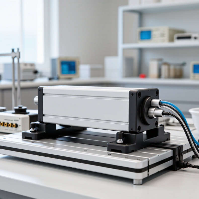
Before choosing a piezoceramic actuator, define the motion your mechanism actually needs. Is it a 10-micrometer adjustment, a rapid vibration, or a repeatable shift under load? Measure travel at the working point, not just at the actuator. A flexure or mounting plate can reduce usable motion. Small details matter.
Positioning requirements need equal care. Specify the target step size, allowable error, settling time, and repeatability across the full operating range. A system that must hold a lens steady may need different control than one making frequent scanning moves. Piezo actuators can show hysteresis and creep: the position may not follow voltage perfectly, or may drift after a move. Feedback from a displacement sensor can improve control, but it adds cost, space, and setup work. Sometimes the sensor is the harder part.
Check the load and motion profile together. A stated free-stroke value does not guarantee that travel under your real load. Include the mass being moved, preload, mounting stiffness, and expected operating temperature. Then compare the required bandwidth with the controller and sensor, not just the actuator’s headline response. Leave margin where possible. It is tempting to optimize for the smallest step, but that may overlook settling time or stability. Revisit the requirements with a simple test setup; the first estimate is often incomplete.
| # | Selection dimension | Define your requirement | Useful data and checks | Selection guidance |
|---|---|---|---|---|
| 1 | Motion type and axes | Specify whether the motion is linear, angular, tip/tilt, or multi-axis, and identify the direction of travel. | A single stack actuator primarily produces axial motion. Flexure mechanisms can convert or guide that motion, but their geometry affects travel, stiffness, and force. | Choose the actuator and mechanism together. For guided motion, check that the flexure constrains unwanted rotation and lateral displacement. |
| 2 | Required travel | State the minimum usable stroke, including adjustment range, tolerance, and any travel margin. | Typical piezoceramic stack free strain is approximately 0.05%–0.15% of active length, depending on material, electric field, and operating conditions. For example, a 20 mm stack at 0.1% strain gives about 20 µm of free stroke. | Compare the required travel with the actuator’s specified free stroke, then account for the reduction caused by the applied load and any flexure mechanism. |
| 3 | Resolution and positioning accuracy | Separate the smallest commanded increment from absolute positioning accuracy and repeatability. | Open-loop piezo motion is nonlinear and exhibits hysteresis; the amount depends on drive range and operating conditions. Closed-loop systems use position feedback to correct motion, but actual accuracy depends on the sensor, controller, mounting, and environment. | If the position must be measured and corrected, specify a feedback sensor and define accuracy, repeatability, and resolution as separate requirements. |
| 4 | Load, force, and stiffness | Record the static load, dynamic load, preload, and any force needed at the end of travel. | Under a simplified linear model, loaded displacement is approximately free displacement minus load divided by actuator stiffness: x ≈ xfree − F/k. Blocking force is not the force available while maintaining full free stroke. | Check the force–displacement curve at the intended operating point. Include moving mass, external forces, and the actuator’s permitted preload in the calculation. |
| 5 | Speed and dynamic response | Define the motion profile, operating frequency, settling time, and moving mass. | Dynamic response is limited by mechanical resonance and the attached load. Added mass generally lowers resonance; mounting stiffness and the flexure structure also affect the usable bandwidth. | Evaluate the complete mounted assembly, not just the unloaded actuator. Verify that its response and settling behavior meet the required motion profile. |
| 6 | Operating environment and stability | Specify temperature range, heat sources, vibration, contamination, and whether long-term position stability matters. | Piezoelectric response varies with temperature and operating history. Thermal expansion in the actuator, mount, and workpiece can create positioning drift even when actuator motion is controlled. | For precision positioning, consider temperature control, a thermally stable mounting arrangement, and feedback measured close to the point of interest. |
| 7 | Drive electronics and duty cycle | Specify the available drive voltage, command waveform, update rate, and operating duty cycle. | A piezo actuator is a capacitive load. Required current increases with capacitance and voltage slew rate; a useful estimate is I = C × dV/dt. Continuous high-frequency operation can increase heating. | Match the driver’s voltage, current, and bandwidth capabilities to the actuator and motion profile. Check electrical limits and thermal behavior for the intended duty cycle. |
Note: The figures shown are general engineering guidance, not guaranteed specifications. Confirm stroke, force, stiffness, voltage limits, and environmental ratings against the selected actuator’s datasheet and the requirements of the complete assembly.